Grid Connection
The grid connection point should be decided early in the design phase. It may be decided to split the BESS into two or more distinct units for connection at multiple points in the network. This can be done to allow multiple sections to function independently with BESS support, as well as to provide for redundancy in the system design.
The type of connection should be decided early. If the BESS shall connect to an LV or MV connection point. Most battery systems will not exceed 1500 V DC, as this would bring them into the HV classification range and entail increased equipment and operational demands.
Additionally, it may be difficult to find DC switchgear rated to such high voltages and current.
Usually drive DC link voltages will be between 900 -1100 V. For grid-facing applications the DC link voltage should be above the peak grid voltage. For a 690 V system the wave peak will be ~950 V. The DC link voltage should then be kept above 1000 V to operate without fear of uncontrolled reverse conduction through the inverter switching bridge.
When connecting to an LV network, the BESS can be treated like a generator incomer, though energy flow will be bi-directional. Depending on the AC drive configuration, it may be possible to connect the BESS directly to the network before the output is modulating, and have the drive perform a 'flying synchronization'. Otherwise, conventional synchronizing will be needed.
If connecting to an MV network, it will be necessary to install a transformer to interface the LV drive to the MV network. It may also be desirable to have an isolation transformer for direct LV connection also.
Connecting via a transformer is a more complicated undertaking. Several things must be considered:
Firstly, will the BESS energize the transformer prior to connection to the MV network?
If yes, this will then require conventional synchronization techniques for live/live connection.
If no, it may not be possible to 'black start' the facility from the BESS.
Secondly, how will synchronization be controlled?
Options to use conventional pulse based synchro relays for frequency and voltage matching; or
Use VT direct measured voltage feedback from transformer primary and MV bus to allow the BESS controller to perform its own synchronizing.
Thirdly, the decision on transformer winding ratios so that the BESS can stay connected at all expected MV bus voltage operating points:
• Consider the voltage regulation of the transformer during full load charging and discharging of the BESS.
• Option to select a more optimized voltage ratio between grid and BESS AC output. This may allow for lower DC link operating voltages than a direct connection.
Load Requirements of batteries
One of the most impactful design elements of BESS is the dimensioning of the battery component. What is important to consider is the required power draw or charging current, and the energy requirements. While these two factors are highly correlated, there is the ability to tune for one or another.
When designing and selecting a BESS the project engineer will deal with a battery specialist who will try to select the correct battery package for the application. This will involve creating a usage profile for the system, with an assumed program of charge and discharge cycles.
As an example, this may include 300 events of charge discharge cycles from 60-40 % SOC at 1 C, with 5 events every year where the battery will act as spinning reserve, discharging at 2 C from 80 - 20 %, and one event in 5 years where the battery discharges from 90 - 10 % at 2 C. all this is considered over a design life of 10 years.
This is just an illustrative example. But based on these requirements, a battery size and configuration will be specified that can sustain the necessary Crating (power flow), DOD, and still fulfill these requirements at its end of life.
Figure 2 depicts an example of a battery usage profile. This may be a typical process profile, which can be combined with other use profiles, along with information about the daily frequency, DOD, and yearly occurrences, to arrive at a lifetime usage profile of the battery.
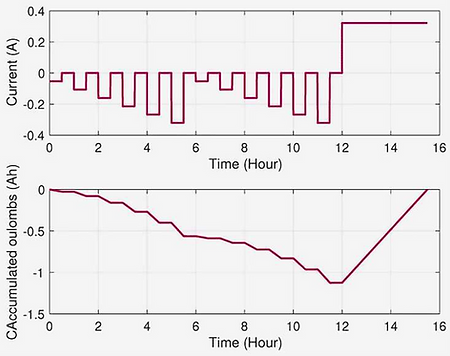
Figure 2 - Example of a battery usage profile
It is important for owners and operators to understand that battery life is based on several assumptions. The load profile at design stage, consistent temperature of the battery room, and a lack of battery abuse, to name but a few.
Battery abuse may include storage at very hot or cold temperatures, excessive over or under charging, or subjecting the battery to voltage spikes.
Division of Batteries
Different suppliers will have differing terminology. However, the "battery" is often used as a general term to refer to a common collection of battery arrays. The lithium-ion interface unit will make a cell. The electrochemical reaction inside this cell generates a voltage that is typically in the range of 2.2 - 4.4 volts at the extremes of SOC.
Though the exact values should be provided by the supplier for the actual cell chemistry that is being purchased.
These cells are then assembled in series into a battery module to generate a more useful voltage. This will differ between systems, but a typical battery module voltage is around 50 volts. These modules are then arranged again in series to create a string.
Typically, the string voltage will be the final voltage level suitable for connection to the DC link. 20 x 50 V batteries in a string will give a nominal voltage of 1000 V DC.
A collection of strings in parallel is referred to as an array. A typical battery setup will have several arrays connected in parallel. Individual batteries will usually have a fuse and contactor to disconnect the pack in case of internal faults such as overheating. Each string may have basic fuse protection, and each array may have a collective load breaker switch, to perform isolation for maintenance.
This type of arrangement should be considered at the design stage. It may be desirable to have the ability to operate the BESS at reduced capacity by isolating an array from the pack.
This would also be required for maintenance or because of unit failure. Also, it may be a requirement to have battery arrays across multiple rooms to create redundancy in case of fire or other failures.

Figure 3 - The graph of a typical lithium Ion cell voltage as a function of SOC
Battery Energy Management
It is critical that owners and operators understand how the SOC on their battery system is calculated and how this relates to actual energy storage. This is strongly correlated to SOH. In consumer applications, often a manufacturer will hide the true SOC of a battery from the user to give consistent user experience despite declining battery SOH.
An example of this is when a battery manufacturer may state O % or 100 % SOC on the battery user interface, when in fact the SOC is only ever between 20% and 80% true SOC.
They may do this to preserve battery SOH by preventing owners from overcharging or discharging, as well as give consistent battery lifetime performance by dynamically changing the SOC limits behind the scenes to be in line with the expected battery level, so that the user is not aware of lifetime degradation in the battery capacity.
However, in industry we often expect to have qualified, professional operators and engineers who need to know the true state of equipment so that they can safely extract the most performance from these systems, and schedule necessary maintenance and replacement.
What is important for a BESS is not necessarily the SOC, but the useful energy that is available.
As the battery package ages, the SOH will decrease. As the SOH decreases, the same % of SOC will indicate less energy content than previously. If a spinning reserve operation required a calculated 80 % - 20 % SOC during termination time, it may be necessary over the years to increase the SOC range for this operation, e.g. 85 % - 15 % SOC, as the aged battery will store less useful energy over a given SOC range.
To determine how battery ageing is progressing, the operators should keep logs of battery SOC usage for given operations. This can often be done in an automated manner by energy metering systems, to collect data over a long operating time, and identify trends.
From time to time, the battery should undergo a dedicated SOH test, to obtain more accurate ageing data. This may be done in conjunction with the battery OEM. A proper SOH test will involve controlled charge and discharge cycles to compare SOC and actual energy storage of the battery. This can be compared against the calculated battery lifetime degradation estimates. It may identify faster ageing than expected, and inform them that operational procedures should be changed, or that premature replacement is necessary.
It is important for critical BESS applications to have a well-known SOH. If the synthetic spinning reserve does not sustain operations for the planned time, it will invalidate the original purpose of the BESS.
When multiple BESS systems are installed, a SOH test can be performed by exchanging energy between the systems. This can provide a highly controllable and stable load and source for charging and discharging the BESS. As well as minimizing losses by avoiding the use of a load bank to dissipate discharge energy.
Black start considerations
If the BESS is intended for use in black start scenarios, it must be possible to start the BESS system with only its own stored battery energy, and possibly other UPS power supplies. For this we must consider at least three items:
• Control circuit power source
• DC link pre-charge power source
• Transformer magnetization (where relevant)
The control power will normally be provided by other UPS power supplies in a facility; however it is possible to take a supply from one of the battery strings or arrays. This must be considered and engineered for. Any AC motor options on the drive should be swapped to DC motors, such as cooling fans and cooling medium pumps, and appropriate power supplies installed that can take the relatively high DC string voltage and convert to the control voltage, usually 24 V DC.
In any case, for a black start the BESS will require a stable power supply.
The DC link in the AC drive will have large capacitors for filtering and smoothing purposes. If starting from a true black start scenario, and the DC link has been de-energized, it will be necessary to pre-charge the DC link capacitors. This cannot be done by a direct low impedance connection to full rated voltage, such as a DOL connection of a battery array to the DC link.
The sudden inrush of charging current may damage the capacitors. The pre-charge is a process of slowly energizing the capacitors, until they reach a level where the link can be connected to high power, low impedance sources.
The pre-charge process can be done in many ways, including using in-line current limiting resistors. But if planning to black start the BESS from battery power, a special system must be optioned to allow this to occur from battery power.
The AC drive is usually capable of magnetizing its own transformer. It can apply a ramped voltage to avoid the saturation effect and zero crossing closing issues that can occur with normal AC energizing of transformers.
This must be engineered to ensure that other elements of protection and switchgear will not be affected by this.
Such as keeping the transformer primary side disconnected from the main grid until voltage has stabilized.
Battery Safety Design
The risks of lithium-ion batteries are somewhat well understood by experts in the field. However, their relatively new deployment in service has meant that industry experience is not as well developed as it is for other hazards, such as lead acid batteries, or conventional electrical hazards.
From an electrical standpoint, working with lithium-ion batteries carries similar risks to other LV battery systems. It is not possible to remove the battery terminal voltage, and any incidents such as a short circuit will be backed by a high current capacity, low impedance energy source.
Appropriate caution is needed when working electrically with such systems.
An additional risk with lithium-ion batteries is the risk of thermal runaway. If the cell should exceed a critical temperature, from either internal short circuit, or external factors, such as an adjacent fire, the chemistry inside the cell is such that a reaction will take place.
This reaction is exothermic, generating heat, and having a positive feedback loop to generate further reaction and heat.
In this chemical reaction the battery will generate its own oxygen to sustain the fire. This means that the fire is very difficult to extinguish, and often only thermal management is possible to attempt to prevent other batteries from becoming involved.
Some manufacturers claim to have mitigation systems in their battery packaging, such that a thermal runaway will not spread to adjacent packs. Often these systems are integrated with a segregating frame structure and exhaust duct feature, so that the resultant toxic gases are extracted from the battery room.
It must be noted that the smoke generated in a thermal runaway is highly toxic. In the case of a battery fire all personnel should evacuate the area and ensure correct breathing equipment is used and the room well-ventilated before re-entering for a damage assessment.
Figure 7 shows a photo of Lithium Fire Intervention Mask by MediSafe. Lithium battery fires are highly toxic. Without proper PPE and training, the only course of action is to evacuate the area and avoid breathing the toxic smoke. Any well managed industrial site with BESS should have proper PPE for rescue and firefighting activities.

Figure 7 - Lithium Fire Intervention Mask
For battery thermal management, there is the option of water cooled and air-cooled systems. There have been issues with leaking water-cooled systems causing a short circuit and subsequent electrical fire, which has led to thermal runaway in the batteries.
Battery Room
For the reasons mentioned in battery safety, it is advisable to have a dedicated room to house the BESS batteries. During installation and commissioning, it is necessary to delay the installation of the batteries themselves until after all firefighting and fire detection equipment are installed and commissioned, and any gas ducting is installed and finished.
In the meantime, cabling and battery rack frames can be installed.
The location of the battery room should be considered so that it is not adjacent to any critical areas, such as control rooms. DC cable length to the AC drive location should also be considered.
Direct Connected DC Link
A direct connected DC link will have the batteries directly electrically connected to the DC link of the AC drive, with no active components in between. In practice the batteries will be contained in a separate room, with necessary electrical isolation and protection devices in place to allow for start up procedures, safe disconnection in an emergency, and regular maintenance of the battery array.
However, in normal operation, the BESS drive DC link will be directly electrically connected and float at the same voltage as the attached battery bank.
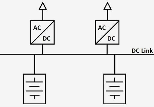
Diagram: Batteries directly connected to the DC link
Direct DC Link Advantages
This design is generally less expensive than an indirect DC link arrangement, as well as having a smaller footprint. This is because the design does not require additional DC-DC converter(s) to interface the battery bank(s) to the DC link of the BESS drive.
Additionally, this setup can have greater overall efficiency as the round-trip power flow between the batteries and DC link is direct, rather than through the DC-DC converter.
Direct DC link Disadvantages
There are serval drawbacks to a direct connection setup inherent to its design, mainly concerning decreased system flexibility. The drive DC link voltage will not be directly controllable by the BESS drive because the DC link is directly connected to the battery bank. The DC link voltage will thus be strongly correlated to the SOC of the battery bank, as well as the dynamic power flow of the battery bank.
This can lead to difficulty for the BESS drive to maintain its switching strategy and effectively modulate an AC waveform when drawing from a variable DC link voltage. This may manifest as a lack of controllability for active and reactive power flow from the BESS, and at extremes of operation, disconnection of the BESS from the network.
This is not a fatal flaw but must be considered when accessing the required operational limits of the BESS, and the operational modes and profiles of the intended application.
The lack of DC link voltage controllability occurs for two main reasons. The battery SOC is highly correlated with battery cell voltage. Thus, the battery SOC directly impacts the DC link voltage. While over a long-term time horizon the operator has control of battery SOC, this may place limits on the allowable SOC for the batteries, and limit BESS dynamic capabilities, especially at very high and low battery SOC.
Secondly, there are dynamic effects of power flow on battery voltage, and hence DC link voltage. When the BESS drive sources power to the grid it will take this energy from the batteries. As the batteries discharge, they will have an internal voltage drop roughly proportional to discharge current (there are also complex electrochemical interactions that introduce some non-linearity to the voltage drop). This battery terminal voltage drop will manifest as an instant drop in DC link voltage as the BESS supplies power to the grid.
Greater power draw will result in greater instant voltage drop, and this may create issues with the switching control logic of the BESS drive at high power draw.
Conversely, the opposite phenomena will occur when the BESS drive sinks power from the grid. When the BESS charges the batteries, the same internal battery voltage drop will occur in the opposite direction, appearing as an instantaneous increase in battery terminal voltage.
This instantly increases the DC link voltage. This effect must be known to the designer so that they do not allow the BESS drive to sink too much power at high SOC and dynamically exceed the voltage rating of the DC link. This can damage the capacitors on the DC link, and in practice will likely result in the BESS disconnecting from the grid to protect itself, leading to local grid instability from the sudden transient that results.
What these SOC and dynamic effects mean in practice, is that a BESS with a low SOC will not be able to source large power levels, as the DC link voltage may collapse and result in lack of modulation and disconnection, and at high SOC, the BESS will not be able to sink large power levels, as it risks DC link over voltage and disconnection.
This places restrictions on the operator, where they must anticipate the required actions of the BESS, if it shall need to source or sink power, and where they should aim to keep the system SOC for the appropriate response. Operator considerations are covered in more detail later.
Another disadvantage of direct connected BESS systems is that it may be difficult to balance the voltage between different battery strings. This limits the design topology to simpler systems with a battery array consisting of only a single battery string.
Indirectly Connected DC Link
In contrast to direct connected DC links, the indirect DC link connection places a DC-DC converter between the conventional BESS drive DC link and the battery array. This solution is generally more expensive, less efficient, and takes a larger installation footprint, but can lead to a much more flexible and adaptable BESS that supports interconnection of multiple battery arrays.
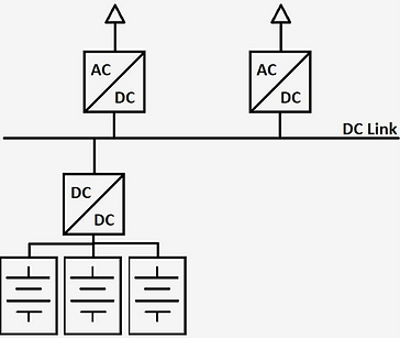
Diagram: Indirectly connected system. Several battery arrays are connected to a single DC/DC converter
Indirect DC Link Advantages
The indirect DC link design addresses all the shortcomings of the direct link design. The introduction of a DC-DC converter decouples the BESS DC link voltage from battery SOC and dynamic charge/discharge battery terminal voltage. This allows for a fully controllable DC link voltage and more stable and predictable performance of the BESS modulation.
The BESS peak charge and discharge power will still be dictated by battery Crating, however with correct selection of DC-DC converters the SOC operating range and dynamic performance will be increased when compared to a direct DC link design.
Additionally, several DC-DC converters can be connected in parallel to a common DC link.
This allows for dynamic connection and disconnection of multiple battery arrays, even when those battery arrays are at different voltage or SOC. Additionally, through control of the DC-DC converters, SOC balancing can be done between battery arrays. This allows for great flexibility in the BESS, with the possibility to service battery arrays while keeping the BESS operational at reduced overall capacity. Alternatively, damaged battery arrays can be disconnected for safety, while maintaining system operation at reduced capacity.
Another advantage of DC-DC converter arrangements is that the BESS drive DC link can be pre-charged by the DC-DC converter connection. Normally a sufficiently large AC drive will have to have a dedicated separate pre-charge circuit to perform initial energisation of the DC link, as direct connection of a low impedance voltage source (such as DOL batteries, or AC grid input) can lead to a large current inrush to the capacitors, damaging the DC link.
The flexibility of indirect BESS systems can be further leveraged by including alternative asynchronous voltage sources to the DC link in parallel to the battery arrays. Such an example may be a variable speed PMG shaft generator attached to a large variable speed motor, such as a ship's main direct drive engine, or alternative energy sources like hydrogen fuel cells.
Such an asynchronous source can be rectified and connected in parallel to the DC link, allowing for highly bespoke and integrated systems tailored to specific industry requirements.
Indirect DC Link Disadvantages
The disadvantage of an indirect DC-DC converter arrangement is the inclusion of the DCDC converter(s). This adds cost, complexity, inefficiency, and engineering
challenges. The increased cost of equipment is an obvious outcome of added equipment. As well as the necessary footprint for installation.
Additional considerations are increased HVAC cooling requirements for the converter room, perhaps dedicated cooling systems for the DC converter, and necessary control and monitoring communication with the BMS.
The inclusion of a DC-DC converter in the BESS charge/discharge loop introduces inescapable losses due to imperfect conversion efficiency. Even a highly efficient unit at 98-99% will decrease overall system efficiency, especially when considering that the power will flow both ways, and that the converter will be active the entire time the BESS is connected.
Other factors to consider are the maximum power limitations of the DC-DC converters. If the intended battery C rating design for the BESS increases, this will add necessary size to the DC-DC converters to flow this much power. Increased DC-DC converter size will generally lead to increased quiescent losses in the converter. This will reduce the overall efficiency of the system further.
When considering the BESS from an FMECA perspective, the inclusion of the DC-DC converter adds failure modes to the system, however this can be largely mitigated by dividing the battery connection into multiple parallel arrays.
Pre-Conditioning for Operations Mode
When creating the operational philosophy and operational procedures for a plant with BESS, it should be considered what the acceptable SOC range for the batteries is in different operating modes.
For example, if performing a regeneration operation, where stored process energy is to be recovered, the batteries should be a suitably low SOC to accept the amount of process energy to be regenerated, as well as accept the charging currents necessary for the rate of the operation. Failure to properly condition the BESS before the regeneration event may result in failing to capture all the stored energy, or even the operation being halted if there is no alternative way to dissipate the energy stored in the process.
Perhaps more important is keeping the SOC sufficiently high for virtual spinning reserve operations. If the BESS is to be an energy reservoir during a critical task, it is essential that there is sufficient SOC available to carry out this task. It should be noted that it may not be advisable to always keep the BESS at a high SOC, as this may shorten battery life. The battery supplier can advise on the best operating conditions to prolong the battery life.
Preconditioning can be achieved by automated means, such as functions in the PMS that will charge or discharge the BESS to the correct SOC for an operational mode. Alternatively preconditioning can be a part of written procedures that operators must comply with as part of a plant activity.
There are pros and cons on each side. With increased PMS complexity often comes cost and EPCIC time increases, as well as less system flexibility. However, written procedures are always at the mercy of human error and rely on competent operators.
Thermal Events and Damage Inspection
In the course of normal operation, a lithium ion battery may suffer a thermal event due to age, internal fault, or excessive external heat sources. In such a case the BMS will hopefully detect this occurrence and issue a shutdown and isolate command for the battery string, and perhaps the entire BESS.
After a battery system has suffered a thermal event, it will be necessary to perform a damage assessment before considering the next steps, and eventual return to service of the system. In general, after a thermal event, it is advisable to contact the battery supplier for advice and assistance in how to proceed.
If the thermal event was isolated to a single battery module, then hopefully this was due to BMS action, such as disconnecting the battery string, and isolating the battery modules from the DC bus connection. In such a case the damage should be limited. The BMS should indicate which module was faulty. After ensuring that the room is well ventilated, and the thermal event was indeed contained to the single battery module, personnel can enter the room and remove and inspect the faulty module. It may be advisable to use breathing equipment and air quality measuring equipment for the first room re-entry.
Lithium thermal runaway events can be long lasting. Even if the module appears to have stopped the thermal reaction, it is possible that the reaction is proceeding at a smolder internally and may flare up at any time. There should be a plan to safely and quickly remove the faulty module from the rack and place it in a quarantine area, such as a water bath, or other suitable fire safe area.
Once this module is removed, the other modules can be inspected for damage, and their BMS and terminal voltage checked to attain the module health. If the other modules are OK, and a replacement module can be installed, it may be possible to return the system back to service in relatively short time.
Of course, if the fire is extensive, the only option may be to stop all operations and perform an ESD and evacuation of the plant.
Emergency Shutdown
A BESS powered by lithium-ion batteries is like any other energy source, when considered from an ESD perspective. When planning for ESD functionality care must be taken to make sure that all battery connections are disconnected, both at the string level, but also at the module level.
Well-engineered battery systems will have ESD compatible options available when selecting the system.
Designers must consider how the system shall be restarted once the ESD condition is removed. That is, the correct sequence of reconnection and ensuring that fire suppression and detection services are back online before energizing the BESS.
Evacuation Planning
Failing to plan is planning for failure. Any facility can have an incident. Depending on the processes and work activities at the plant, incidents may require evacuation of the plant. A lithium battery fire may be one such incident. Depending on the plant arrangement, and the quantity of batteries on site, the correct response to a fire may be to rely on passive and active installed fire suppression systems and evacuate all persons from the area.
Making sure to have a plan to safely stop any operations beforehand, such as via an ESD system.
Care must be taken not only for the thermal elements of the fire, but also the smoke from the lithium fire. This smoke is highly toxic to breath. Gas extraction systems should be in place for batteries installed in confined spaces, such as indoors in a dedicated battery room. If the battery building is a stand alone facility, or perhaps containerized, evacuating personnel should be instructed and trained to try to get upwind of the fire, to avoid smoke inhalation.
The evacuation meetup point should be as far away from the battery area as possible.
There may be different meetup points for different scenarios, depending on the facility. If the meetup point is downwind of the fire, it will be vital to make sure the fire wardens move people to an upwind locations, and anyone who must remain downwind should have proper breathing PPE that is rated to filter lithium smoke.
Changing Control Parameters with Age
As lithium batteries age through time, discharge cycles, and environmental factors, the energy capacity of the batteries will tend to decrease. Regular SOH tests can give the owner an idea of the trend of the battery condition and inform the changing operating procedures that should be followed to ensure the BESS performs the intended functions.
As the batteries age, a given cell battery, or SOC, will no longer reflect the same available energy content as when the system was new. This will mean that long discharge operations may have to start from a higher SOC as the battery ages, and charging operations should start from a lower SOC.
Operational target SOC figures should be updated over time to reflect the actual condition of the BESS capabilities.
Operational procedures should also be revisited over time, to ensure that the BESS has the capability to operate in all intended use cases, including at the extremes of battery C level, such as high power discharge scenarios. Increase in internal battery resistance over time may place extra stress on battery cooling systems, and limitations on how long high power operations can be safely sustained.
Shutdown of Batteries
When performing a long term planned shutdown of a BESS, it is necessary to ensure that the battery system is correctly shut down. If only isolated from the main power connection, it may be that the module BMS is still powered up, running directly from the energy in the battery module.
Over time this will drain the module below its safe minimum voltage, and may result in a damage battery module. If this mistake is made for an entire battery array, it will be an expensive one.
The manufacture will have a procedure to safely isolate and deenergize the batteries for long term storage or disuse. This will include an ideal SOC, temperature range, and how to disable the BMS to avoid battery drain. There may be a procedure for periodic cell voltage check to ensure that the batteries do not drop below the critical cell voltage level.